 Creating a bridle assembly diagram
|
Command |
Path |
|
Create Bridle Assembly Diagrams |
Spotlight > Rigging |
Create simple assembly diagrams for selected bridles in the drawing. Each diagram includes a schematic drawing with labeled parts, including a connected hoist used as a down leg, and an optional parts list. The diagrams can be placed on a sheet layer or design layer, and arranged in one or more columns.
To create a bridle assembly diagram:
Select one or more bridle objects, and select the command.
The Create Bridle Assembly Diagram dialog box opens.
Click to show/hide the parameters.Click to show/hide the parameters.
|
Parameter |
Description |
|
Place On |
Sets the location of the bridle assembly diagram |
|
Design Layer |
Places the diagram on the specified design layer; select a design layer from the list |
|
Sheet Layer |
Places the diagram on the specified sheet layer; select a sheet layer from the list |
|
Settings |
|
|
Include parts list |
Places a parts list on the diagram, to display the Name, Short Name, and Count of each bridle part. The short name can be edited when Managing bridle parts. |
|
Update existing objects |
Updates the existing bridle assembly diagram to reflect changes to the selected bridle. Deselect the check box to create a new diagram instead. |
|
Size |
|
|
Height/Width |
Specify the dimensions of the diagram |
|
Number of columns |
If multiple bridles are selected, sets the number of columns for the arrangement of the bridle assembly diagrams. For example, if nine bridles are selected and three columns are specified, the diagrams will be arranged in three columns with three diagrams in each column. |
Set the parameters for the bridle assembly diagram.
A diagram is created for each selected bridle. If multiple diagrams are created, they are arranged in the specified Number of columns.
To print one diagram per sheet, place the bridle assembly diagrams in one column on a sheet layer. Set the diagram size to match the Printable Area dimensions specified in Page setup. From the Page Setup dialog box, set the Vertical page count to match the number of selected bridles.
Click and drag the bridle assembly diagram to reposition it. To reposition the parts list independently from the assembly drawing, click the control point at the bottom of the parts list, and click again at the desired location.
Use the Text menu commands to edit the font, size, and style of the text in the entire assembly diagram (see Formatting text), or apply a text style (see Using text styles).
The parameters can be edited from the Object Info palette.
Click to show/hide the parameters.Click to show/hide the parameters.
|
Parameter |
Description |
|
Name |
Displays the name of the associated bridle object |
|
Show Parts List |
Toggles the display of the bridle parts list |
|
Size X/Y |
Enter the dimensions of the bridle assembly diagram |
|
Update Object |
Updates the bridle assembly diagram to reflect any changes to the selected bridle since the diagram was created or last updated |
|
Activate Bridle |
If the bridle assembly diagram is on a design layer, selects the associated bridle object. If the diagram is on a sheet layer, activates the layer where the associated bridle is located. |
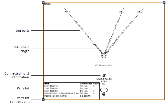
Bridle assembly diagram for a three-leg bridle
